There are following categories of handover (also referred to as handoff):
Hard handover means that all the old radio links in the UE are removed before the new radio links are established. Hard handover can be seamless or non-seamless. Seamless hard handover means that the handover is not perceptible to the user. In practice a handover that requires a change of the carrier frequency (inter-frequency handover) is always performed as hard handover.
Soft handover means that the radio links are added and removed in a way that the UE always keeps at least one radio link to the UTRAN. Soft handover is performed by means of macro diversity, which refers to the condition that several radio links are active at the same time. Normally soft handover can be used when cells operated on the same frequency are changed.
Softer handover is a special case of soft handover where the radio links that are added and removed belong to the same Node B (i.e. the site of co-located base stations from which several sector-cells are served. In softer handover, macro diversity with maximum ratio combining can be performed in the Node B, whereas generally in soft handover on the downlink, macro diversity with selection combining is applied. Generally we can distinguish between intra-cell handover and inter-cell handover. For UMTS the following types of handover are specified: The most obvious cause for performing a handover is that due to its movement a user can be served in another cell more efficiently (like less power emission, less interference). It may however also be performed for other reasons such as system load control. The different types of air interface measurements are: The UE supports a number of measurements running in parallel. The UE also supports that each measurement is controlled and reported independently of every other measurement. Further reading: 3GPP 25.331 |
Further reading: 3GPP TS 25.303, 25.331
During the cell search, the UE searches for a cell and determines the downlink scrambling code and frame synchronisation of that cell. The cell search is typically carried out in three steps:
Step 1: Slot synchronisation
During the first step of the cell search procedure the UE uses the SCH's primary synchronisation code to acquire slot synchronisation to a cell. This is typically done with a single matched filter (or any similar device) matched to the primary synchronisation code which is common to all cells. The slot timing of the cell can be obtained by detecting peaks in the matched filter output.
Step 2: Frame synchronisation and code-group identification
During the second step of the cell search procedure, the UE uses the SCH's secondary synchronisation code to find frame synchronisation and identify the code group of the cell found in the first step. This is done by correlating the received signal with all possible secondary synchronisation code sequences, and identifying the maximum correlation value. Since the cyclic shifts of the sequences are unique the code group as well as the frame synchronisation is determined.
Step 3: Scrambling-code identification
During the third and last step of the cell search procedure, the UE determines the exact primary scrambling code used by the found cell. The primary scrambling code is typically identified through symbol-by-symbol correlation over the CPICH with all codes within the code group identified in the second step. After the primary scrambling code has been identified, the Primary CCPCH can be detected and the system- and cell specific BCH information can be read.
If the UE has received information about which scrambling codes to search for, steps 2 and 3 above can be simplified
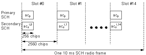
The Synchronisation Channel (SCH) is a downlink signal used for cell search. The SCH consists of two sub channels, the Primary and Secondary SCH. The 10 ms radio frames of the Primary and Secondary SCH are divided into 15 slots, each of length 2560 chips. Picture above illustrates the structure of the SCH radio frame.
The Primary SCH consists of a modulated code of length 256 chips, the primary synchronization code (PSC) is transmitted once every slot. The PSC is the same for every cell in the system.
The Secondary SCH consists of repeatedly transmitting a length 15 sequence of modulated codes of length 256 chips, the Secondary Synchronisation Codes (SSC), transmitted in parallel with the Primary SCH. The SSC is denoted csi,k in figure 20, where i = 0, 1, …, 63 is the number of the scrambling code group, and k = 0, 1, …, 14 is the slot number. Each SSC is chosen from a set of 16 different codes of length 256. This sequence on the Secondary SCH indicates which of the code groups the cell's downlink scrambling code belongs to.
Summary of the process:
| Channel | Synchronisation acquired | Note |
| Primary SCH | Chip, Slot, Symbol Synchronisation | 256 chips The same in all cells |
| Secondary SCH | Frame Synchronisation, Code Group (one of 64) | 15-code sequence of secondary synchronisation codes. There are 16 secondary synchronisation codes. There are 64 S-SCH sequences corresponding to the 64 scrambling code groups 256 chips, different for different cells and slot intervals |
| Common Pilot CH | Scrambling code (one of 8) | To find the primary scrambling code from common pilot CH |
| PCCPCH *) | Super Frame Synchronisation, BCCH info | Fixed 30 kbps channel 27 kbps rate spreading factor 256 |
| SCCPCH **) | | Carries FACH and PCH channels Variable bit rate |
*) Primary Common Control Physical Channel
**) Secondary Common Control Physical Channel
Further reading: 3GPP TS 25.211 25.213


